Hacking: Put a larger battery in an APC Back-UPS ES 350 or 450

Introduction

In the video below I cover adding a larger battery to an APC Back-ups 350 or 450.

Items You’ll Need

A 12V 9Ah lead acid battery
A Dremel tool with cut off wheel.

The Hack

The hack takes advantage of the fact that the 350, 450 and 550 APC UPSes use the same enclosure.  The 350 and 450 have extra supports molded in to support a smaller battery.  We need to remove these supports so the larger battery fits in the compartment.

Conclusion

This is a nice upgrade for those times when you need a little extra run time.

Notes: Wiring an 8 Wire Stepper Motor

Introduction

I’ve been working on a project that required 3 stepper motors. Well Ebay is the best place to get them cheap. Not many of them are 8 wire these days.

Superior Electric M061-FD-6102 Specifications

Leads: 8
Voltage: 11.2V
Current: 0.44A
Step: 200/rotation

Wiring diagam


drive 1 ---------[red]-----)   (-----[green]------------ drive 4
                           )   (
                           )   (
          |----[black]-----)   (-----[orange]--------|
     +V --*                  0                       *-- +V
          |----[white]-----)   (-----[white/black]---|
                           )   (
                           )   (
drive 2 ---[white/red]-----)   (-----[white/green]------ drive 3

Build a Small 10W LED Grow Light for Plants

Introduction

We like to garden inside as well as outside. And wouldn’t you know it, we don’t get much sun in the house. I built this grow light to use on a 4 plant hydroponic garden I built. My test subject for this light will be herbs.

Overview

The colors we are interested in for our light are red and blue. Different LED lights you can buy have differnet ratios of these two colors. There are excellent articles on the internet describing how plants use these two colors. Now if you want to view your plant’s natural beauty then this is not the light for you. For this light I used red and blue LEDs. I used 3 red LEDs for every Blue LED. Hopefully this provides some good results. If you want to view your plants then you’ll have to build a light using white LEDs.

Specifications

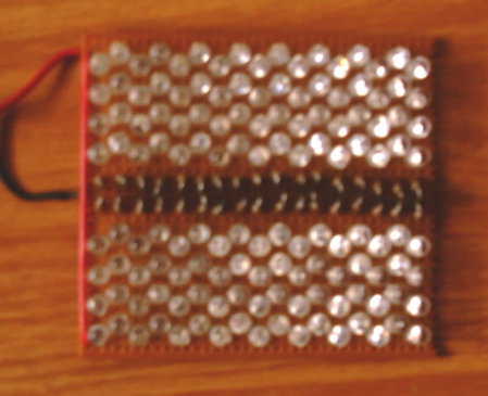
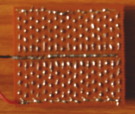
I built the light on perf board. See the pictures for the layout. The light draws 10.7 watts of power and runs on 12V. 1.5W is dissipated in the resisters. I used 136 LEDs and 34 100 ohm resisters.

Construction

Please use the pictures as a guide for construction. Each row contains a 100 ohm resister and four LEDs in series.

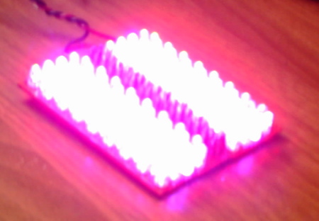
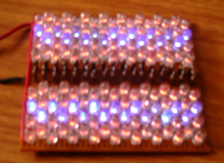
Greatly dimmed so you can see the LED colors.

Top view of Light.

Bottom view of light.

How Much Light Do You Need?

This is prob the biggest question. Depending on what you are growing you’ll need from 10W to 40W per square foot. Lettus and herbs will need 10W to 25W per square foot. And vegetables will need 25W to 40W per square foot. What you are aiming for is 50% to 70% of the watts per square foot used by an HPS light. For example if you use a 250W HID light you would need at least a 100W LED light.

What Can I Grow?

The ratio of red to blue is important to plant growth. This light has a high percentage of blue light. This makes it well suited for non flowing plants such as herbs.

Conclusion

This is an extremely bright light. It should provide enough light for a small garden. By small I mean less than 1 ft by 1 ft.

Build a Small 5V and 12V Power Supply with Optional PIC Programmer

Introduction

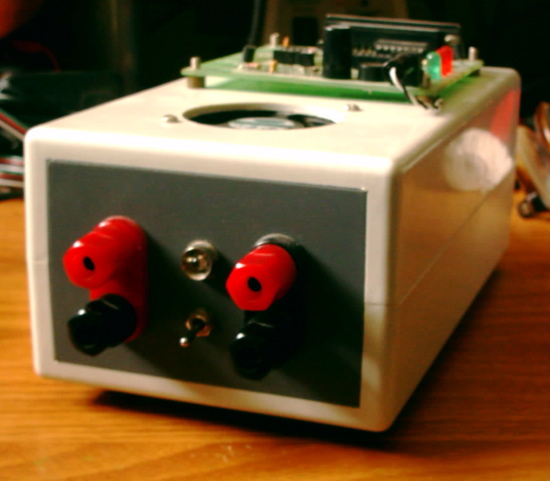
I needed a bench top power supply for prototyping PIC microcontrollers. I also had my PIC programmer looking for a home. Well combining the two together created a nice piece of equipment.
The PIC programmer is an old parallel version.  It can still be useful for many people.  I have upgraded to a USB version these days.

Overview

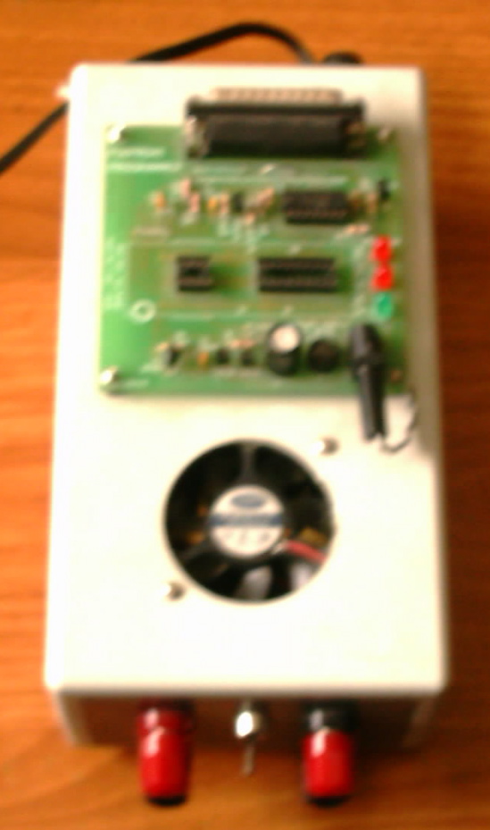
This is nothing more than a PIC programmer kit mounted on top of a power supply. You can buy/build the PIC programmer of your choice. The programmer gets its power from the power supply.
The power supply provices 5 volts at 1 amp and 12 volts at 1 amp. When plugged in the power supply powers up the programmer. The front switch controlls a relay which supplies power to the front terminals.

Schematic

The schematic lists the part values. This is a standard power supply design based on the LM7805 and LM7812 voltage regulators.

Right click on the image to view/save a full size version

Pictures

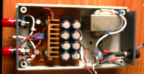
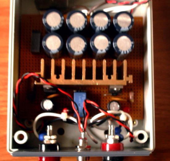
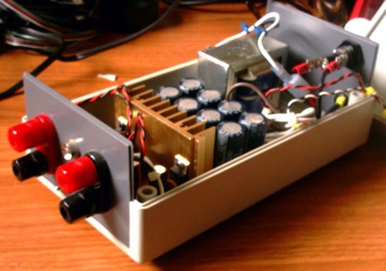
Here’s some pictures of the inside of the power supply.

Conclusion

There’s nothing better than a PIC programmer built on top of a bench top power supply. Just add a prototyping board and a computer and you’re good to go.

Build A 30W 50 Ohm Dummy Load

Introduction

For testing out transmitters every ham should have a dummy load. The project I’m describing here is useful up to 30W. The parts used could allow up to 50W but there is no vents in the chassis.

The Parts

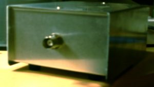
  • One small metal box
  • One chassis mount BNC connector
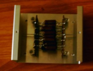
  • 26 1.3K 2W resistors.

Construction

The 26 resistors were soldered in parallel. One end was connected to the chassis. The other end was connected to the center pin of the BNC connector.

Conclusion

I realize that there isn’t much here. But hopefully the pictures give you some ideas. Use whatever parts you have on hand. The goal is to get a resistance load of 50 ohms. Good luck.

Modding And Hacking A Christmas Light Controller

Introduction

For under $10 you can buy christmas light sets that flash the lights in different patterns. These sets have a small controller that animates the lights. The light set I chose cost $7.99 and were purchased from Big Lots. The lights can be removed from the controller and plugs installed.

Disclaimer

This project works with items that run off of AC mains. Only qualified persons should consider attempting this project. This project is meant as a guide. Your controller may be different from mine.

The Parts List

  • 1 x set of chasing Christmas lights
  • 3 x green multi outlet extension cord
  • 6 x crimp butt connectors

Tools

  • Wire cutters
  • Wire strippers
  • Crimp tool

Prepping The Controller

1. Remove the lights from the packaging.
2. Identify the main power leads going into the controller. It should be two wires connected to the AC plug. You may want to place some tape on these wires to identify them. We will not be altering these connections.
3. Next we need to identify the wires connected to the lights. Follow each wire to the first light it is connected to. We are going to leave one light connected to each wire. This will let us identify each channel. Cut the wire that is connected between light 1 and light 2. The controller I had gave me three channels. So I had three lights.
4. The last wire to cut is the return wire for all the lights. About 12 inches from the controller cut the wire. Strip this wire back 1/4 inch.

Prepping The Extension Cords

1. Cut the AC plugs off the extension cords. You should be left with the AC receptacles at the other end.
2. Separate the cord back 2 to 3 inches.
3. Strip each wire back about a 1/4 inch.

Putting It Together

I bet you’re wondering why we left one light connected to each channel. Its an easy way to identify the wires.
1. Twist together the wire without a light connected and one wire from each extension cord. Using a crimp connector secure the connection. This forms our common wire.
2. For each of the wires with a light connected do the following. Cut the light off the wire and strip the wire back 1/4 inch. Twist this wire with the un-crimped wire from one of the extension cords. Using a crimp terminal secure the connection.

Notes About LED Lights

Some sets of LED Christmas lights will work with the controllers. The LED rope lights sold by Costco work fine. LED light sets with 35 lights work fine. Home Depot is also selling LED lights that work as well.
The controller rectifies the AC into pulsating DC. Many LED light sets have half the LEDs wired to handle one half of the AC cycle. And the other half of LEDs are wired to handle the other half of the AC cycle.

How Many Lights Can Be Connected

Many controllers were design to run 150 to 200 lights. My controller ran 150 lights and drew 0.6A of current. My controller has 3 channels. That works out to 0.2A per string of lights.
Using standard Christmas light limits what you can do. At 0.2A per channel the max number of bulbs would be 50. That’s only one string of lights per channel.
Using LED Christmas lights gives you a great show. A string of 50 LED lights I have use 0.05A of current. That means that we can use 4 strings of lights per channel. That’s 200 LED lights per channel or 600 LED lights per controller.

Conclusion

This project was a great way to animate my holiday lights. Don’t forget to check those after Christmas sales for the best deals.

Build A POE Injector To Remotely Power Your Gear

Introduction

Information on building your own POE adaptors. I didn’t want to install UPSes everywhere in the house. My access point is centrally located in my house. It has a plug right by it but no UPS. My home office on the other hand has a couple of hours of backup. Since I already ran the lan cable its a quick jump to add POE and have wireless access when the power goes out.

This information is for 10/100M ethernet.  For 1G ethernet it is better to buy a POE switch.

DISCLAIMER

The information on this page worked for me. I may not work for you. This information is provided as-is. Use at your own risk. You should have experience with basic electrical wiring. You should also own a multimeter and a soldering iron.

Important POE info for 10/100M ethernet

lan cable function
Pin 1 <-> data
Pin 2 <-> data
Pin 3 <-> data
Pin 4 <-> DC Positive Wire 1
Pin 5 <-> DC Positive Wire 2
Pin 6 <-> data
Pin 7 <-> DC Negative Wire 1
Pin 8 <-> DC Negative Wire 2
Voltage: 48V max (if you want to go that high you need to make sure your equipment will accept it)
Current: 350ma (500ma max)

Simple POE Injector

For my POE project I will be using couplers that snap appart. These couplers have RJ45 plugs. These things are not rated for 100mbit but should work just fine.

First break appart the connectors. Use the table above to determin which wires in the connector we need. For me it was red, green, white, and brown. There is a wiring standard that covers the wire colors so most likely you will cutting the same wire colors. Cut the wires as close to the RJ45 connector as you can. Strip the wires back 1/4 of an inch. When done one half will be missing some wires and the other half will have wires for making connections. Twist together the ends of the red and green wires. Then twist together the ends of the white and brown wires. Do the above for both connectors.

If you’re like me you’ve got a collection of AC wall warts. If you don’t start collecting now. Also if you don’t you’ll be hacking on your wall wart that came with your access point.

Next we need to cut a notch in the plastic housing for the power cable. Notch the half that has the extra wires. The notch should be large enough to allow the wires to pass through when the connectors are put back together.

This completes the prep work for using the injector on your projects.

An Example:  POE for the D-Link DWL900AP+

The AC adaptor DWL900AP+ is 5V. The unit has a built in voltage regulator capable of accepting up to 36V. A search through my adaptor collection yielded a 9V adaptor with the correct size and polarity connector. The unit ran fine with the adaptor connected. My adaptor had a white line on the cable wire marking the positive wire. Cut the cable 4 to 6 inches from the end. Unzip both cables back 1/2 of an inch. Strip the wires back 1/4 of an inch. Connect the positive wire to the red and green wires. Connect the negative wire to the white and brown wires. Do this for both conectors. Solder the wires and cover with electrical tape. Re-assemble the couplers. Lable the coupleers so you know which connector goes to the equipment/switch and which connector carries the power. Test the setup by connecting a lan cable between the injectors and measure the voltage on the power jack. If everything is OK plug the power jack into the DWL900AP+ to verify its operation. If it all tests good then you are ready to deploy.

The POE/DWL900AP+ deployment was very successfull. The cable lenth is around 50ft. Testing so far has shown no negative impact. Now when the power goes out I still have wireless access for my laptop.

Conclusion

POE can be very usefull. It sure beats putting UPSes all around the house.